The crossover
The enclosure was now ready, including surface finishing, the drivers had been fitted, and the internal wiring of the drivers had been done and sealed with Araldite, leading out to the crossover chamber. Now was the time to take SPL measurements and stare at the curves, in preparation for the crossover design ordeal. I have great faith in the creative potential of staring at curves. Look inside the brain of any mathematician studying obscure journals, or inside what goes in lieu of a brain in a schoolboy staring at curves of topless sunbathers, and you'll see all sorts of creative surges passing through the brains. Curves do that to you, and I was all set to do some serious staring.
I had already taken impedance measurements of individual drivers. From that data, I had seen the low Re (3.6 Ohms) of the Kevlar midbass units, and so I had decided to wire them in series instead of parallel. The TG25 tweeter was a healthy 5.6 Ohms or so, IIRC.
How long does it take someone to take SPL readings of one pair of midbass units, and one tweeter, when one has SW working with one's computer and has a Panasonic mic capsule which has been tested in test recordings before? Half a day? One day?
It took me much longer. It felt like much, much longer than it took.
First of all, my SPL readings just wouldn't work. This was October 2005, before the Asawari cabinets were built. I was trying them on the factory-bought speakers I have, not on any DIY drivers. I was expecting a flattish line from about 200Hz to 20KHz (won't go below about 200Hz with the MLS time interval I can use in my living room). But I got strange things. If I used a sampling rate of 24KHz, I got a strange rolled-off curve. If I used higher sampling rates (as I must, to take accurate readings of the tweeter), I got no MLS spike at all. I posted on the Speaker Workshop forum and on diyaudio. I was totally stumped (I would become intimately familiar with this feeling of stumpedness over the next few months). I was trying the same things over and over, night after night, changing various settings, cleaning RCA jacks, playing with signal levels, testing sine wave readings (which always worked beautifully), and generally alternately cursing and praying. Guys on the forum were generally trying to help, and one of the members on diyaudio actually gave me a clear pointer to the cause of the problem, but because of my indisciplined debugging style, I missed it completely. I was wondering whether SPL measurements are at all possible with a USB-connected external sound card. I was wondering whether my investment in this sound card, imported from S'pore with great trouble, was now going to be a waste.
This is the problem that Angshu walked me through, I've referred to this story elsewhere. He was in Bombay that night, on one of his short, hectic official visits. He was as clueless about the specific cause of my problem as I was, but he had years of experience in debugging SW problems. So, at ten in the night, sitting in a hotel room in South Bombay after a long day's work, he started speaking with me on the phone, and walked me through a long two-hour process. We got it working in the end; it was past midnight. I can only imagine how tired he must've been.
The problem was with the way various sampling rates are implemented in Creative Soundblasters. This family of cards implements hardware sampling rates of multiples of 12KHz only. Other sampling rates are derived from these by resampling. This means that there's hardware-level sampling implemented for 12KHz, 24KHz, and 48KHz. For 44.1KHz, it's read at 48KHz and resampled. In my crazy, non-systematic style of debugging, I had not realised that 44.1KHz is failing but 48KHz is working. So I had concluded that "high sampling rates" are not working. There was also a problem of level setting --- my levels were sometimes too low.
Angshu made me disconnect the mic, and just put a loopback cable on the sound card, and measure the sound card's impulse response, not SPL graph. I have now realised that this measurement of impulse instead of SPL is a life-saver. It has gotten me out of jams many times later. When I did impulse measurements, I was getting clean spikes at 24KHz, but none at 44.1KHz. He also helped me set the gains to ensure I was getting a tall enough spike at 24KHz. I then tried 48KHz and, with the right gain settings, I got the spike!! I still remember the feeling of relief which swept through me, dog-tired, depressed, and sweating, that midnight. And Angshu must've silently sent a thanks-giving prayer, knowing he would now be able to get rid of this pain in the neck and go to bed.
I then switched to SPL readings in loopback mode, and saw the sound card's SPL curve coming out neat and flat. Then I disconnected the loopback cable, switched over to the mic, and took some actual SPL readings. They worked. I almost couldn't believe my eyes. They've worked ever since.
The critical things are
- With a Soundblaster, make sure you use sampling rates of either 48KHz or 96KHz. Lower than 48KHz are anyway no use for SPL readings for xo design purposes. And other sampling rates like 44.1 and 22.05KHz work for all other kinds of signal shapes, but not for MLS spikes.
- Use appropriate recorded signal levels. Your impulse reading must show peaks of at least 500 (on a scale of -32000 to +32000, for a 16-bit digital resolution). Yes, the number is 500, not 5000. I never got MLS spikes more than 10000, though sine waves can easily be recorded at full resolution (+/-20,000 or more).
- It's always a very good idea to use a loopback cable and measure the FR curve of your soundcard using a package other than SW. I recommend Rightmark Audio Analyser strongly. This graph will tell you whether the high sampling rates are working and the upper end of the sound card's response is flat enough. What if you have a card for instance whic supports 96KHz sampling rate but always rolls off the upper end after about 25KHz with an analog filter? RMAA will show up all this, without you having to go through the pain and frustration of having to learn to use SW.
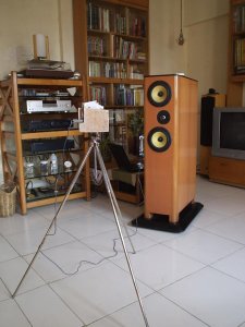 Some people want to know: is this sort of USB-connected external Creative Soundblaster really usable for speaker design, with all its problems? My answer is a resounding "yes", once you know how to work around the problems. These cards are inexpensive, reliable, and the newer versions give you 96KHz sampling rates. Some (the Audigy) even give you 6 or 8 channels, allowing you to test out crossovers in real time using digital simulators available with SoundEasy or LspCAD. I have seen first-time DIY builders investing in really expensive professional sound cards, and I've always wondered why. I still wonder, sometimes. :)
Then I experienced another glorious glow of stumpedness when I tried taking SPL measurements of the finished Asawari a few months later. My SPL graphs showed strange jagged edges which I couldn't eliminate, try as hard as I might. Desperate, I fell back on impulse measurements, and found that I was getting a small spike just before the first room reflection from the floor. This small spike was really screwing up the SPL curves. After a lot of heartburn and head-scratching, I decided to try fixing the mic on my tripod without the wooden jig I had built, and Viola! (or whatever it is that they say in your part of the world) the problem disappeared.
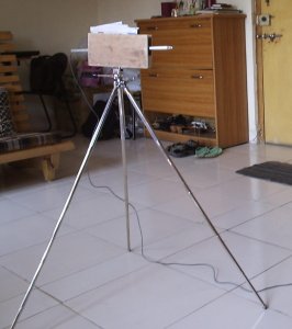 A word of explanation here. I had fixed my Panasonic mic capsule and mic cable to a quarter-inch aluminium tube, and the mic was potruding out one end of the tube, fixed in place with cellotape. So I had an aluminium wand for the mic, smooth and light for easy measurements. I had then built a wooden jig with a nut at the bottom, into which I could stick this wand. The nut of the jig allowed me to fix it to a camera tripod.
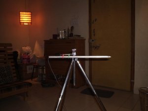 I discovered that if I dropped the wooden jig and used string to tie the wand directly to the camera tripod, the preliminary reflection spike disappeared from the pulse measurements. The photo on the right shows the wand fixed with two rubber bands to the ballhead's handle on the tripod -- it will expand to a much larger version of the photo if you want a closer look. It's only after you try taking accurate measurements that you realise how problems come from unexpected quarters. Vance Dickason didn't tell you nothin' about nothin'.
Once this hurdle was crossed, I took measurements of both the midbass and tweeters, and tried building a crossover with them. This was the tweeter curve I got: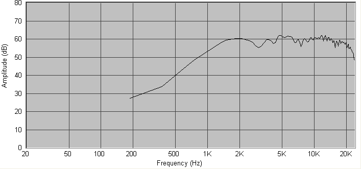
And this was the midbass units' SPL, both drivers in series: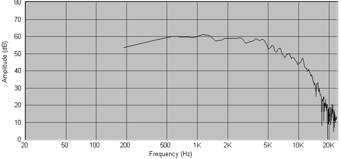
The small sawtooth-like jagged peaks beyond about 5K in the tweeter response are because of interference of tweeter output reflected off the midbass units. Apparently this is quite common for tweeter responses which are on baffles where midbass units have a raised profile.
I used SW's built-in stock crossover insertion feature to insert fourth-order crossover components and used the optimisation feature to get them to align to precise low-pass and high-pass goals. Anyone who has used SW or any other speaker design and modelling package will know what I'm talking about. Angshu had predicted that I'd get the crossover done in an hour once the SPL measurements were in place, and indeed, I now had a crossover schematic in place, which seemed to be giving me nice individual rolled-off curves for the woofer and tweeter: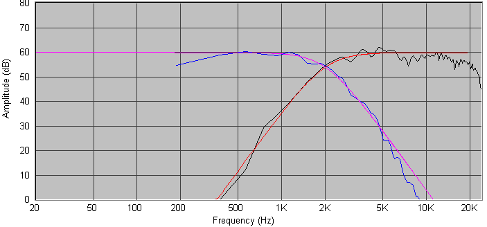
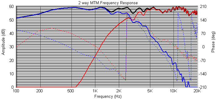
When one combines the woofer's graph with the tweeter's, one should get a flat SPL curve for the total speaker. I tried combining my graphs and landed up with a curve which was quite okay at the ends, but had strange jagged edges stretching for about one octave on either side of Fc, with peak-to-trough heights of 8dB or more: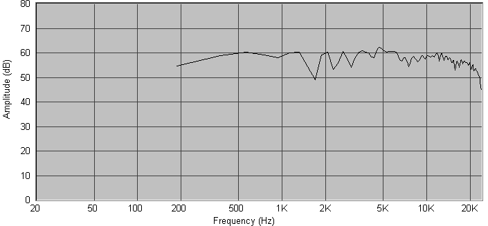
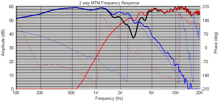
When one reverses the polarity of one driver and combines the two graphs, one expects to get a deep notch of perhaps 20dB or more at Fc. I tried reverse-combining, and I got no notch at all. I just got jagged peaks and troughs just like the straight-combined graph: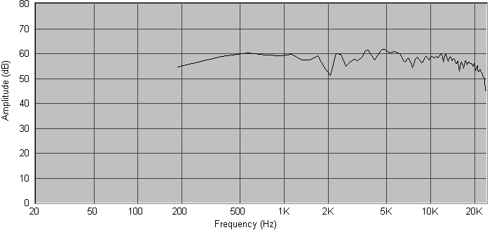
At the risk of sounding repetitive, I was totally stumped. There was nothing in the books about this.
I asked on the forum -- the records show 15 May 2006. I got all sorts of answers, many of them helpful. Here I first encountered one of the basic concepts of crossover design: minimum phase. This term was to haunt me for quite some time after that, and is still haunting me, as I explore three-way crossover design. Friends on the forum patiently walked me through the phase related issues, but couldn't fix the problem. Then John Krutke of Zaphaudio fame, a seasoned designer, pointed me to Roman Bednarek.
Roman was a turning point in my quest to understand crossover design. His approach was quite different from Angshu's. Angshu designs crossovers by plugging in stock crossover topologies in SW, and then asking SW to optimise the values to get precise curves. When things go right, Angshu can arrive at a pretty usable crossover topology in an hour. Roman builds topologies "by hand", by adding one component at a time, watching each component's effect on the SPL and phase curves. He says he rarely uses the optimiser. He hand-tunes both the topologies and the component values of individual coils and caps to get the curve just where he wants it. And Roman is a veteran user of SW. I don't think Roman's approach or Angshu's approach produces better-sounding speakers, but Roman's approach probably allows him to fix troublesome situations better. Like mine. There were others on the forum who too advised me to start serious hand-tweaking: see this post for instance. This advice was teaching me a totally new way of looking at crossover tuning.
In parallel with my discussions with Roman, I continued to take inputs from members on the forum, and in three days, I had fixed the jagged-graph problem. The cause was my sound card. My sound card, the Creative Soundblaster Digital Music MP3+ USB, has randomly varying latency. This means that when the computer generates a pulse signal out of the sound card, the pulse will sometimes emerge in half a millisecond, sometimes after a delay of three milliseconds, sometimes after five. This delay is called latency, and latency is not a problem per se, but randomly variable latency of my kind certainly is. What had happened with my SPL readings of midbass and tweeter is that the two SPL readings had been recorded with two completely different latencies -- it was as if I had shifted the mic position between the readings. As a result, the two readings were totally out of phase, to a random degree. Hence, when combined, the midbass and tweeter graph were showing me a badly out-of-phase, interfering summing signal. Such out-of-phase signals will sum with a jagged graph.
I learned how to take multiple phase-coherent readings with my sound card. It is a workaround, and this is something most people with more stable hardware don't know about. No wonder Angshu couldn't fathom the cause of my problem: he's never worked with such "creative" sound cards, the poor deprived soul that he is.
So now I knew how to take phase-coherent SPL readings, and also to use the "Remove Excess Delay" function of SW to make the phase curve readable and meaningful. (Roman actually guided me a lot here, writing long, lucid emails patiently.) And I now had a summing SPL curve where the midbass and tweeter summed nicely without any jagged edges. I still have all his emails.
But I still didn't have the reverse null of 20dB -- I was getting a null of 8dB or less. I looked deeper, again with the help of friends on the forum and Roman. And discovered this was because at the Fc, the midbass was not in phase with the tweeter: there was a small but significant phase difference. That's when I learned one of the important limitations of the automatic slope optimiser: they optimise only the SPL, not the phase.
So I started hand-tweaking the component values to try to get the phases of the midbass and tweeter to align. And struggle as I might, they didn't align. When I got the phase right, the SPL was way out of league. When I got the SPL right, the phase was out by dozens of degrees. I turned to Roman and Angshu for help.
Roman designed my crossover for me.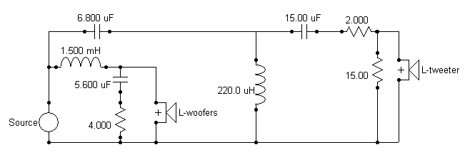
He told me to forget the 2KHz Fc that I was aiming for: he thought it would be too low for the tweeter I was using. He designed a crossover at 2.8KHz, perfectly phase coherent and with a fairly flat SPL. I had sent him my SPL curves in a .SWD file, and he sent me a ready-to-use crossover back in the same file.
I looked at this crossover and realised I could never have arrived at it using Angshu's plug-and-play auto-optimised technique. Roman uses resistors in series with shunt caps or shunt coils to control the curve at the "knee" of the crossover, and also uses a large entry-level coil on the woofer's low-pass crossover to handle the baffle-step compensation problem. Now both Angshu and I are studying all the crossovers Roman has published on his Website for his projects. They're very interesting.
Another valuable insight I gained from all this was asymmetric slopes. Till then, I had naively assumed that when two signals are being summed to get a flat sum, the degree of "negative slope" in one signal should equal the "positive slope" in the other. This assumption stemmed from some sort of basic belief in the symmetry of complementary forces. So, if the low-pass filter was giving me a 24dB/octave slope at and beyond the Fc, the high-pass must also have a 24dB/octave slope, if I had even a remote chance of getting a flat sum. Right? No, not necessarily.
It is perfectly possible to get a flat sum by combining a third-order low-pass with a second or fourth-order high-pass. Nothing magical about it. When I thought more about it, I realised that any experienced speaker designer would know this, but if one just assumed things based on engineering intuition, one might miss this point. And this insight is key to getting phase and SPL to align in troublesome crossovers. Crossover designers often use asymmetric slopes at the Fc in order to tackle phase mismatches, I discovered.
I decided to just go ahead and build what Roman had given. And this crossover remains the one in the Asawari, apart from the one contribution I was to make: tweeter level tuning.
| Previous: Enclosure | Next: Crossover tuning |
