From passive to active
I have been fascinated with active crossovers from the time I learned about them. One of the first things I had read about them was while studying active filters. Among other things, I read about LR4 circuits on Rod Eliott's site and in Randy Slone's "Audiophile Projects Sourcebook". I bought and read parts of Lancaster's "Active Filter Cookbook". Then, when I encountered Seigfried Linkwitz' super-site, I saw what he had done with the Phoenix (this was in the pre-Orion days) and understood how an active crossover is much more than active filters.
In parallel, I was exploring crossovers from a traditional passive starting point. I got talking with an acquaintance who had built the classical active crossover using John Pomann's LR4 kits and a BSC kit. He said that imaging was not very good. I asked my veteran speaker-design friends and they told me that a textbook LR4 is as useless for good crossovers as an off-the-shelf "Hi-fidelity Second Order Crossover" is in the passive world. They taught me about phase coherence, and impedance non-linearities (which of course don't affect active xo), and told me that the only way to start designing active crossovers was with real SPL+phase measurements of real drivers on a real enclosure, and using a crossover modelling program. Since SW had no support for modelling active xo, and I didn't have any money or any knowledge to help me buy a commercial speaker design package, I just ogled at what others did, and played with what I had.
Then, after the Asawari was built, the old active xo bug bit me again. I wanted to try to see, just on paper, what an active xo would look like for the Asawari, if all I wanted to do was replicate what the passive xo did.
The active xo described here has never been built.
A friend, who has a demo copy of LspCAD 6, said he would help. He said we could use this program to quickly try to do one long design session, and see where would reach with the crossover. So I exported the FRD and ZMA files from SW for the actual Asawari woofers and tweeter, and trundled over to his laptop. These SW files loaded into LspCAD almost immediately, and within minutes, we could see a screen with the two driver symbols, each with its own SPL and phase graphs. These looked the same as the curves I see in SW, so I was comforted that we were not really in alien territory after all.
Attempt 1: stock LR4
We first tried putting in stock LR4 blocks for each of the drivers, an HP for the tweeter and an LP for the woofer. The two resulted in decent looking SPL graphs, but their SPL was out of sync. Try as we might, we couldn't get their SPL and phase to both fall in place together. This was clearly evident in the reverse null: that was barely 8dB deep. It clearly would not do. This was strongly reminiscent of the problems I had faced designing the passive xo of the Asawari, till Roman had stepped in.
Attempt 2: copy the passive
We then took a long look at the Asawari's passive crossover and wondered whether any of the lessons learned from there could be used here. We had seen how Roman had taken recourse to asymmetric slopes to get his crossover to fall into place. We decided to try the same thing.
The passive crossover has an electrical second-order low-pass on the woofer, and an electrical third-order high-pass on the tweeter. We decided to try that. We specified an Fc of 2800Hz for both, because that was the final Fc of the passive xo.
We were not very happy with what we got. There appeared to be a wide and shallow dip in the summed SPL at the crossover point. So we decided, why not just shift the tweeter's Fc a little lower? We changed just the tweeter's Fc to 2600Hz, and the summed SPL began to look better.
We tried optimising the two filters. We specified targets as per the filter definitions. For the woofer's LP filter optimisation, we specified a target of second-order LP, and for the tweeter, a third-order HP. After some time, when the curves had gone through many fine real-time tweaks from the optimiser, we didn't like what we had got. The slopes didn't sum very well, neither in the magnitude nor in the phase. The null was still fairly shallow, but better than the previous 8dB.
Attempt 3: new optimisation
We then had a brainwave. Since the eventual acoustic slopes of the passive xo were fourth-order slopes, we said why not optimise both the LP and HP for fourth-order? We did this. And finally, we began to see slopes emerging which looked close to what we'd seen with the passive xo.
We did a bit of hand-tweaking of the values after the optimiser had done its job, and then looked at the reverse null depth. It was almost 18dB. We tried tweaking the tweeter's HP filter's Q, reducing it from a value of 0.95 which the optimiser had given, to a lower 0.75 or so. The phase coherence immediately improved, and the SPL hardly changed.
We now had a convincing active xo, but the levels were not matching. We tweaked the gain value for the tweeter to bring its magnitude graph visually into alignment with the woofer. Then we rounded off all the arbitrary values to somewhat more nice-looking ones (e.g. replace an Fc of 3217 with 3200 and so on) and were relieved to see that the xo wasn't too sensitive to these tweaks: its magnitude and phase coherence remained visually unaffected.
The BSC
In the passive xo, there was no separate BSC circuit; one large inductor in the path of the woofer had done the honours. I had no such option with an active xo. So I decided to add a shelving filter. I decided to just try a 400Hz "knee" frequency, and add the block and see what happened. There is a gain control in this filter block, with a default gain of 6dB. I decided to play with that value to see where it would lead me, visually.
I found that it did more or less what the passive xo was doing. We now knew we had a usable starting point for an active xo, if we wanted to build one.
I am sure that if we build this active xo, we will need to tweak the levels of the woofer, tweeter, and the BSC knee frequency and gain. But tweaking levels is the easiest part of tweaking an xo. The larger issues of tweaking slopes or even shifting the Fc, are much more difficult to do and take more time and effort. We are fairly confident that our active xo will probably not need any of that, because we have already heard the passive version of this xo.
Lessons learned
- Modern modelling tools are very easy to use for first-draft designs, if you have good measurements. No one can help you if you don't have actual measurements.
- Even with modern modelling tools, you can't get a good xo done unless you have some experience. Look at the sequence of steps we went through, and you will see that we would have been totally clueless had we not fallen back on what Roman had done with the passive xo. We finally merely mimicked his asymmetric xo.
- Level tweaking of the individual drivers is necessary, and can't be done on paper. They will need actual listening. What looks like a "maximally flat" magnitude graph may not sound right in the living room, as happened with the passive xo I had built.
- The optimiser can't be left to its own devices to give you a nicely summing and phase-coherent crossover. (No optimiser can; if they could, I would not have needed Angshu and Roman's help with the passive version.) However, it is very useful. I could see that its optimising action really creates strange sequences of filter blocks which I would never have been able to arrive at by hand. For instance, if you start with a fourth-order electrical filter, with its two active stages tuned to the same Fc, the optimiser will pull one stage's Fc way back and the next stage's Fc way forward, and will give you a resultant slope which really conforms closely to the target. When you see the resultant Fc and Q values, you realise that you would never have tried such values manually. It may put the Fc of the second stage of a two-stage LP filter two whole octaves beyond the acoustic Fc. For instance, when I was trying an electrical LR4 at 2500Hz, the optimiser shifted the Fc of the second stage to about 10000Hz. Yet, if I removed that stage, considering it redundant, the slope immediately distorted to an unacceptable degree. I was quite amazed.
I am certain I will build an active xo for one of my speakers one day --- I have been brainwashed sufficiently by all that I have read of the writings of Seigfried Linkwitz and Rod Elliot and all the others on the forums. When I do, it'll most probably feed into LM3886 amplifiers. And who knows, maybe I'll build the passive xo first, and then build the active version based on that.
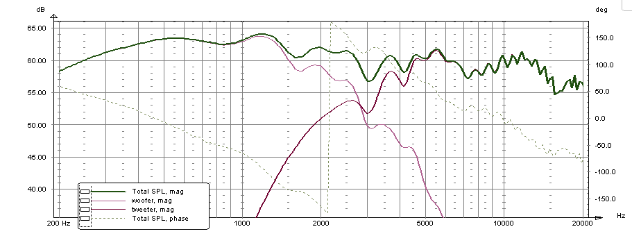
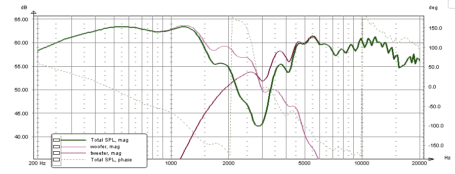
Since it is not possible to save files in the demo version of LspCAD, my friend took screen snapshots of the design and the graphs. If you go to the previous page ("Crossover") in this sequence of pages, you will see the passive crossover details. Here, I am recording the active xo block diagram, the summed magnitude graph, and the phase inverted magnitude graph.
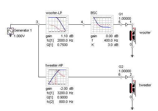
The image below shows the block diagram of the xo. Using spreadsheets created by some members on diyaudio, one can convert the Q and Fc values into actual R and C values for plugging into the active filter circuit diagrams. I will leave that as an exercise for myself, later, if I choose to build one.
The woofer's LP filter has an electrical Fc of 2000Hz, while we are talking of a final acoustic Fc near 2700 or 2800Hz. The Q is 0.75. It is a second-order filter. Following it is a BSC block with a "knee" frequency of 400Hz and a K of 3dB. I presume the K specifies the level difference between the two sides of the knee. Whether 400Hz and 3dB will be right can only be decided after listening. The tweeter's HP is an electrical third-order HP filter, with the first stage carrying an Fc of 3200Hz and a Q of 0.9. The second stage, strangely carries an Fc of 800Hz, way, way below the acoustic Fc. But it definitely helps. Eliminating it changes the slope and the phase coherence.

The summed magnitude and phase inverted magnitude curves are given below:


If you want to see what the passive crossover's curves look like, check the Crossover page.
| Previous: Crossover tuning | Next: Sound |
