I had decided to try a lower crossover point in the Mark 2. The SPL and impedance measurements went off without too much problem, once I re-learned Speaker Workshop and recollected how to work with (i) an outboard USB sound card, (ii) an impedance jig, and (iii) set volume control levels.
The woofer and tweeter SPL curves turned out to be as follows:
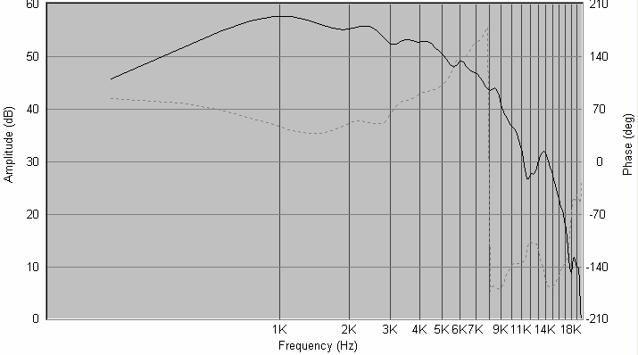
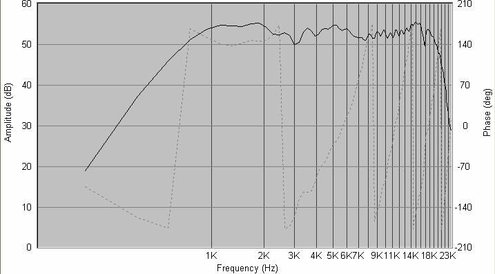
The phase shows less jagged edges than one usually sees in a raw reading because I cleaned it up by adjusting delay. I had to use 19.4msec of delay adjustment to get the phase plots to clean up.
Then I applied a conventional crossover on the woofer and tweeter, along the lines of what I had seen Roman Bednarek do for the Mark 1. This is what I got.
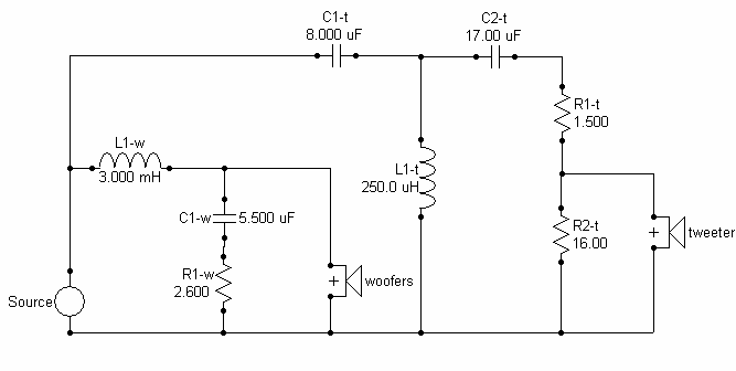
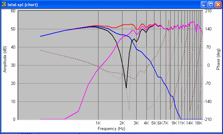
If the fc is the frequency of the sharp point of the notch, then as per the modelled response, I'm getting an fc of 2060Hz or so. Not exactly as low as my original dreams, but low enough for me to meet my design objectives.
The reverse-phase null is quite deep -- deeper than what I've seen earlier. However, the crossover components all appear to affect the phase coherence of woofer and tweeter. Even small tweaks of value seem to make the reverse null shallower by 8-10dB. This means that normal errors of tolerance in value will make the phase coherence much worse than the modelled ideal case. Also, most of the values are non-standard, needing passives in parallel or series sets.
There is a 3-4dB peak in the tweeter response in the highest octave. The official literature of the tweeter says that this is a designed-in feature. The idea is that this peak in the on-axis response will reduce to a flattish curve in a typical listening setup where the listener listens at about 15 deg off-axis.
When you look at the values in the crossover circuit, you know you'll never get those values. Capacitors are the most painful to tune, inductors -- which are made to order -- are the easiest. Therefore, I plugged some real-world capacitor values into the simulation circuit in Speaker Workshop, and tried to see what I get. I'm glad that I finally managed to get an almost identical set of SPL curves with the new values, after tweaking resistors and capacitors. The circuit below can be built -- it has real-world values of caps and resistors. A 2.5-Ohm resistor is a parallel pair of two 5-Ohm resistors, etc. In simulation, I'm getting the 30dB notch just as before. I'm happy.
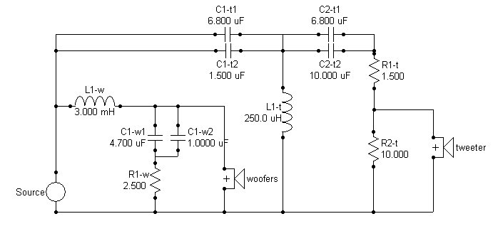
Bought the crossover parts. The resistors are ordinary white-coffin 10W power resistors, as with the Asawari Mk I, and the capacitors are metallised polyester (DEC/MER, yellow cylinders), rated at 250V, from Ramesh Electronics in Kiln Lane, off Lamington Road. They cost me a total of less than Rs.400.
The inductors were a pain. The Bangalore based Corrson has gone out of the DIY audio business, and no one that I know of can make a coil if I give broad specs (wire gauge, value of inductance). Everyone wants to know "how many turns, what former diameter, what length". So I used some online inductance calculators and arrived at a spec -- "X turns of 16 SWG copper over a former so many inches long and so many inches in diameter." I added 10-15% additional turns to ensure that the inductors would be higher in value, not lower. A higher value can always be reduced by unwinding the turns. Then I found a party which was willing to make the coils for me, and they made them well. The bill was a whopping Rs.6000 (about USD 120 at current rates) for four inductors.
They wrapped the coils in long strips of cotton cloth and dipped the whole inductor in varnish, I think. The end-result was excellent, solid and tight, if I wanted it ready-made. But I did not -- I needed to unwind them to bring the value down to the right figure. So I had to unwind that cloth (took an hour to just remove the cloth from four inductors) and sat down with sound card, impedance jig, Speaker workshop and laptop. I found that the 250 uH coils were all between 340-360 uH, and the 3.0 mH coils were roughly 3.5 mH. So I kept unwinding and measuring, till I reached figures which were +/-1 from the desired value in the second significant digit. In other words, I wanted 3.0 mH, and I got between 3.1 and 2.9 mH. For the 250 uH, I got 240-260 uH. That's near enough for me, and the Speaker Workshop inductance readings are never stable anyway -- the readings of the same coil keeps jumping more than this amount even if I don't touch a single wire between consecutive readings. I finally fastened each coil tight with cable ties.
I use 16 SWG copper for inductors. This is about 14 AWG, for my American friends. I think this is thick enough for my inductors, considering I'm not building any low-pass at 200 Hz in a 3-way or 4-way speakers.
I measured the capacitors and resistors too, to get their values close to 1-2% of what the simulation says. I bought capacitors of slightly lower value where possible, plus a dozen 1uF and 0.1uF capacitors, to fine-tune the values if I can by paralleling.
Made a physical layout diagram of the crossover parts on the board.
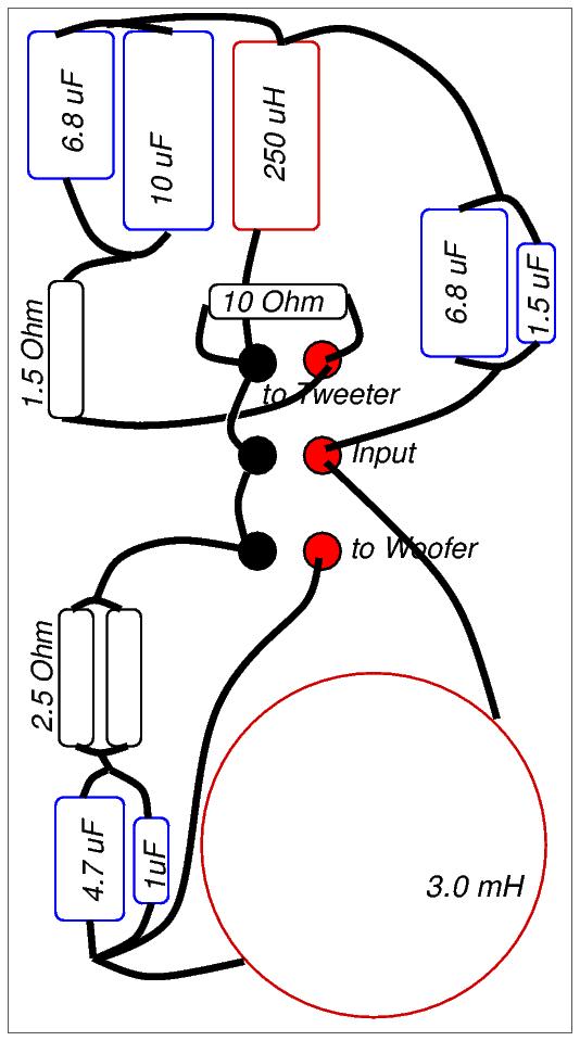
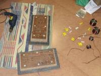
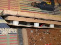
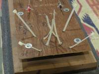
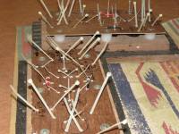
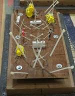
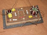
I used my old construction approach of a 3mm-thick plywood sheet as the crossover board. It is mounted just inside the speaker terminals, on 1"-tall nylon spacers of the kind used below cupboards and tables to raise the wooden legs from the floor. I will drill holes in the plywood sheet and mount the parts using cable ties. Then I will solder the parts using point-to-point soldering. I have a lot of 16 SWG enamelled copper wire lying around, having removed a dozen metres of it from the coils while trimming their value. Those will be my point-to-point connecting wires this time.
Just in case there are some DIY builders less experienced than me, I thought I'll put up some photos of how I assemble the physical crossovers. I tie down the components to the sheet of ply using cable ties and then connect them electrically using point-to-point wiring. No printed circuit boards.
Next step: solder the components, fix the boards back on the enclosure, connect the driver cables to the crossover, and see whether it sounds like a real speaker. This bit was finally completed in August 2013.
| Previous: Enclosure | Next: performance |

